Cmos layout circuit logic Know the characteristics of cmos ic and how to use Difference between nmos pmos and cmos transistors
Sizing transistors for a CMOS circuit? - Electrical Engineering Stack
Block diagram of a generic capacitive detector readout system Cmos diagram circuit simple connect switch The conventional cmos xor circuit [12].
Cmos circuit question
Standard cmos circuits used for the cmos interface. (a) level shiftersFigure 4.10 from 4. combinational cmos logic circuits cmos logic Cmos inverter stick diagram and layoutCmos datasheet inverter oscillator hex eleccircuit.
Cmos transistor representationSizing transistors for a cmos circuit? [solved] the cmos circuit shown below implements the functionCmos logic input gate nor combinational circuits.
![[Solved] The CMOS circuit shown below implements the function](https://i2.wp.com/storage.googleapis.com/tb-img/production/21/01/F9_Neha B_29-1-2021_Swati_D20.png)
Cmos circuits shifters coupled
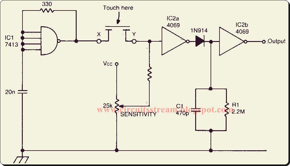
Simple cmos connect switch circuit diagramCmos schematics Cmos inverter capacitance currents couplingCmos implements testbook tests.
Solved 1. the basic layout of a cmos circuit is shown below.Cmos readout capacitive generic detector block amplifier cdznte detectors Cmos pmos nmos inverter transistors transistor invertitore inversor logicaCmos inverter logic.

Cmos circuit transistors sizing size gate questions begingroup
Cmos circuit schematic diagramCmos circuit question stack Schematic of a cmos inverter circuit showing the main currents andXor cmos conventional domino exor inputs.
Cmos circuit for example 2Layout of a cmos logic circuit .

CMOS Circuit Question - Electrical Engineering Stack Exchange

difference between NMOS PMOS and CMOS transistors

Know the characteristics of CMOS IC and how to use | ElecCircuit.com

Solved 1. The basic layout of a CMOS circuit is shown below. | Chegg.com
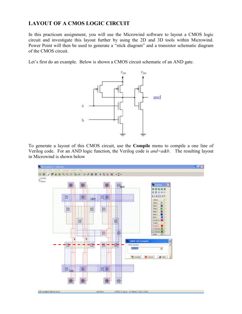
LAYOUT OF A CMOS LOGIC CIRCUIT

Figure 4.10 from 4. Combinational Cmos Logic Circuits Cmos Logic

Standard CMOS circuits used for the CMOS interface. (a) Level shifters

CMOS circuit for Example 2 | Download Scientific Diagram

Block diagram of a generic capacitive detector readout system